Buyer’s Guide: How Manufacturer’s Specify Equipment
Understanding how equipment manufacturers specify their equipment is the first step in finding the right equipment for your production requirements.
 Placement Speed
Placement speed for pick and place machines is measured in terms of “components per hour,” or CPH (sometimes also referred to as PPH for “parts per hour”). This is the rate at which components are picked up, inspected and placed onto a PCB.
Many equipment manufactures use the IPC 9850 standard to determine CPH rates for their machines. This ensures that they are using the same part mix and PCB placement arrays, making it easier for buyers to compare one machine—and one manufacturer’s machine—against another’s. Other manufacturers will design their own PCB for their speed rating and use more accessible pickup locations to get a “faster” rating.
To determine a more “real world” production speed of a machine, de-rate the manufacturer’s stated IPC 9850 CPH rating by 20%. If the manufacturer’s CPH is not IPC 9850, de-rate it by 30%. You can also use our handy online CPH calculator to estimate the “real world” CPH—ignore the top section and use only the middle or bottom.
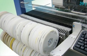
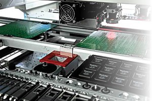
8 mm tape feeders installed on a pick & place machine.
Feeder Slots
Feeder capacity means the number of 8 mm tape feeders that can be loaded onto the machine at one time. Larger components will require larger feeders. You’ll need to find out from the manufacturer how many slots each of the larger tape feeder types—12 mm, 16 mm, 24 mm and up—take up.
Matrix or waffle trays and tube (or stick) feeders will also take up valuable feeder slot real estate. If you’ll need to use trays or tubes, you’ll need to find out the capacity of the available feeders and how many 8 mm spaces they’ll require.
Keep in mind any special component needs you have, including BGA, CSP and odd-form parts.
Part Size
Keep in mind any special component needs you have, including BGA, CSP and odd-form parts.
Equipment manufacturers will give you the maximum and minimum component dimensions that the machine will handle.
In many cases you’ll see multiple component size specs given for a single machine. This happens when there are multiple alignment methods installed on the machine. One method may be faster or more precise, but because it only handles a narrow range of part sizes, an alternate alignment system is included to cover a wider component range. The machine’s software will automatically switch methods as needed.
One thing you’ll want to know is not just the largest size the machine can place, but what’s the largest it can inspect? Some equipment has the ability to handle larger parts than they can inspect.
You’ll also need to know the maximum part height the machine can handle.
On the small end of the spectrum, you’ll want to know the minimum size the equipment can pick, index and place. Most machines are capable of handling 0402 or even 0201 chips. 01005 placement capability is out there, too. In any case, keep in mind that anything 0402 or smaller may require a special nozzle and/or feeder. Check with the manufacturer.
Feeder racks can reduce available board/panel area. Make sure you have the details on this before making your final decision. You don’t want to be caught in a situation where you can’t load all the feeders you need because you didn’t realize the max board size specifications were based off a single feeder rack being installed.
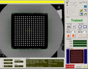
Component Lead Pitch
0.012″ fine pitch is fairly standard for today’s pick and place equipment. If fine pitch capability is required, do not be fooled by manufacturers referencing motor specification or motor accuracy. There is more to fine pitch placement than motor accuracy. It does not matter how accurate a motor is if the machine (system) cannot pick up, inspect, and place fine pitch leaded and ball grid components.
Other important considerations
Feeder racks can reduce available board/panel area. Make sure you have the details on this before making your final decision. You don’t want to be caught in a situation where you can’t load all the feeders you need because you didn’t realize the max board size specifications were based off a single feeder rack being installed.
- Maximum and minimum PCB or panel size and thickness can be critical for some electronics manufacturers. Don’t take the maximum values on their face: feeder racks and waffle trays can reduce available space.
- You’ll also want to make note of placement accuracy.
- If you’re not looking at benchtop machines, the PCB loading method could be important.
- Fiducial recognition, coordinate correction and bad mark detection should be standard for automatic pick and place machines—check to make sure the equipment you’re looking at has these features.
- If you’re looking at automatic machines, how are they programmed? CAD download, teaching camera, bar code readers, MIS and optimization functions and off-line programming can all make the operator’s job easier and your production more efficient.
- Some machines can be optionally fitted with a dispense head for depositing adhesive on the board. If you require this feature, note what the dispense method is, along with dot size and dispense speed.
NEXT: What Will Your Production Require?
This article is a part of the Pick & Place Equipment Buyer’s Guide.